IGBT Chopper/Inverter
8837-BGallery
Description
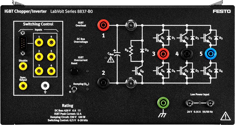
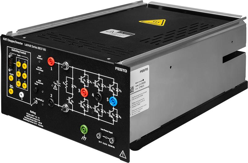
The IGBT Chopper/Inverter module consists of seven insulated-gate bipolar transistors (IGBT) mounted in a half-size EMS module. Six IGBTs are used to implement choppers and inverters. These IGBTs are protected against a variety of abnormal operating conditions, such as short-circuits, overvoltage, overcurrent, and overheat. The seventh IGBT and a dumping resistor allow smooth dissipation of excess energy at the dc bus. The dumping circuit can be activated through the use of a toggle switch on the front panel.
The module switching control section allows 0/5 V pulse signals from either the Data Acquisition and Control Interface, Model 9063, the Chopper/Inverter Control Unit, Model 9029, or any compatible 0/5 V control unit, to be applied to the gating circuits of the IGBTs. The signals are input in the IGBT Chopper/Inverter module through a nine-pin connector.
Six miniature banana jacks can be used as test points to monitor the pulse signals using an oscilloscope. These jacks can also be used to inject 0/5 V pulse signals from an alternate control unit, as well as to inhibit each gating circuit. The IGBT Chopper/Inverter module also includes a synchronization output to trigger an oscilloscope when observing the switching control signals, as well as a switching control disable input that allows all six IGBTs in the chopper/inverter section to be switched off.


