Communications Transmission Lines FACET Board
91028-2Gallery
Description
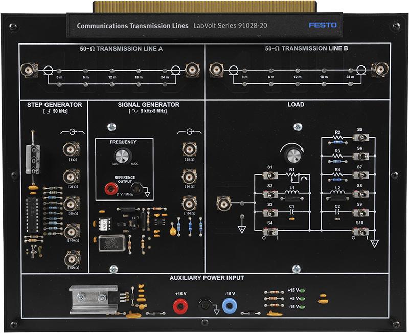
The Transmission Lines circuit board provides students with the theory and measurement skills required to implement and test communications transmission lines. Students first learn the principles and operational characteristics of transmission lines. They then learn how to conduct transmission line measurements under transient (step testing), and sinusoidal steady-state conditions. Finally, students acquire a valuable foundation in the theory and practice of time-domain reflectometry (TDR), as well as impedance matching and transformation.
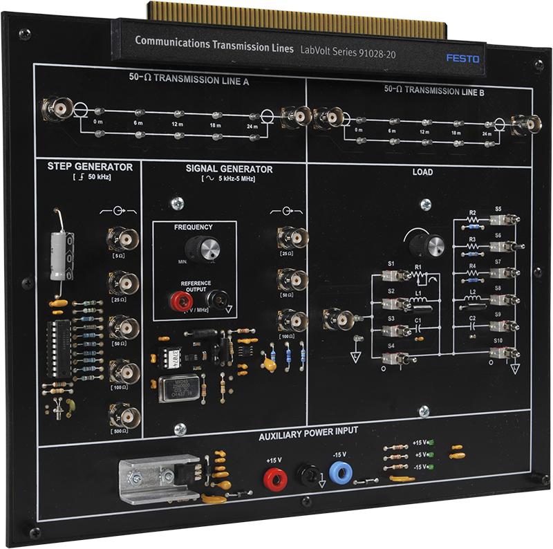
The circuit board uses two RG-174 coaxial cables, each a length of 24 meters (78.7 feet). They can be used separately or connected end-to-end. Each line has five probing points that permit observation and measurements of signals along the line, using an oscilloscope.
Two generators are provided to study the transmission line behavior: a step generator that produces a 50-kHz square-wave voltage for transient behavior testing, and a signal generator that produces a sinusoidal voltage of variable frequency (5 kHz - 5 MHz) for steady-state behavior testing. Each generator has several BNC outputs providing different output impedances.
A load section, consisting of a configurable network of resistors, inductors, and capacitors, permits connection of different load impedances to the receiving end of each line.
The circuit board may be used in the FACET base unit, or as a stand-alone trainer.
- When used in the FACET base unit, the course can be performed through the interactive Learning Management System (LMS) format. Moreover, faults can be inserted into the circuits to allow students to develop troubleshooting capabilities.
- When used as a stand-alone trainer, the course is performed in a conventional way by using the provided student manuals and instructor guides. An external power source is required if the circuit board is used without a base unit.
Topic Coverage
- Introduction to the Transmission Lines Circuit Board
- Velocity of Propagation
- Behavior of a Transmission Line Under Various Load Impedances
- Attenuation and Distortion
- Determining Characteristic Impedance and Velocity of Propagation By Measuring the Distributed Capacitance and Inductance
- Voltage Reflection Coefficient at the Load and Generator with Purely Resistive Impedances
- Transient Behavior of a Line Terminated By Complex Load Impedances
- Detection and Location of Discontinuities on a Line By Using a Time-Domain Reflectometer (TDR)
- Troubleshooting
- Standing Waves and Voltage Standing-Wave Ratio (VSWR)
- Effect of Attenuation on the VSWR
- The Smith Chart, Resonant Lines, and Impedance Transformation
Downloads
Product Fixes
Transmission Lines 5.00.01 to 5.00.02

